Showing posts with label Families. Show all posts

Saturday, April 02, 2011

When you have a hammer, everything is a nail.....

Ok, so not quite true, but one must ask the question, now that '12 supports placing Adaptive Components in project, what are we to do with them?

Well the first answer is, just about anything!!! Remember that AC's can have a single placement point (they don't need multiples) meaning that the family will behave very similar to placing any non-hosted family. I'll let Krista follow-up with a post on this brilliant work-flow, including my suggestion on how to "circumnavigate" the issue of limited category options for AC's.

On to the main subject of this post....

Since time eternal (or at least as long as I can remember) Revit has had a 1D array (ie, define a start point an end point and elements are arrayed between them). However in architecture there are certainly a number of occasions where a 2D array would be far more useful (ie create a "grid" of elements rather then a single row). Now this little technique will not solve all problems, but it may help with some, and inspire others.

My use case is this, we do a number of education facilities at our firm, which means classrooms, classrooms often means regulated "arrays" of chairs or desks, rows and rows of them in fact. So what if we could simple define the outside corners of where we want our furniture, the distance between each row and column, and let the computer do the rest, including dynamically updated if we change the size, interested!?

Enter adaptive components. The first step is to create an AC with a flat plain, that is actually a "void" (thus not visible as a piece of geometry). Each corner (however many you want) is of course an Adaptive Point. Once we have the Void Surface, we can divide it (clever tick huh?) so now we have a grid that we can control with parameters. Did I mention that we can also put the AC into the Furniture Category (kinda useful).


Now that we have our armature, we need some panels to go in our grid. Time for a new family, this time a Panel by Points family (also can be put into the Furniture Category). This family is a little more complicated, you could model your actual furniture here, but my suggestion is to load a family built from the standard template(s). The trick is locating the family in the panel. Here, I've created two sets of crossing reference lines that lock my tablet arm chair to the center of the panel. You could always look at doing an offset, or something else, but for the purposes of demonstration, I decided to keep it "simple".

Once you have your furniture panel, you can load it into your array family. Place the panel (of course you have multiple panels, and allow users to use a Type Parameter to switch one from another) into the divided surface, and now we have a 2D array of chairs. Once that is done, load the array family into your project and start placing.

As with just about anything that uses Adaptive Components, more CPU power is going to be your friend. Regen times can be high with Adaptive Components, though as long as the nested family is not too complex, you should not see anything to far out of the ballpark here.

Wednesday, December 08, 2010

Inspiration from AU

Where did we take that photograph of existing conditions?
Where am I standing while looking at this rendering?


Familiar questions when working with Revit, right? Revit provides no good way to mark, or locate cameras, renderings or photos, right? Well earlier this year I created a generic annotation component to callout "cameras" this came out of the need to identify photo locations on a site. It was nice, but completely manual in nature, particularly in terms of setting the detail and sheet numbers, which also meant it did not update correctly.

Ever since the customizable elevation tags came out I've tried to think of something useful to do with them, sure you can finally "tweak" the OOTB content to look exactly like what you drew on mylar, but really? How important was that? Inspiration finally struck when I was hanging out in the AEC lounge at AU answering user questions, you can use a custom elevation view type to "callout" a photo or camera location!

click for enlarged view

How does it work you ask? First I've got a custom pointer family and body family. These are assigned as a new elevation tag, which is then assigned to a new Elevation Type. The last trick is, when you go to place the elevation, you choose "Reference other view" in the Options bar. From Reference other View you can choose  either drafting views (good for site/existing condition photos) or any view saved as a "rendering" (image) in the project. Once placed you can rotate and adjust as needed, since it is not a "live" view, these annotations will only show up in the view they're placed in. Of course, because its an elevation tag, it will carry the sheet/detail number references when you place your drafting or rendering view onto a sheet.

So, there are a few "drawbacks" to this approach....
  1. You can't actually directly reference a real "camera" (Autodesk are you listening?) but you can save a camera view as a "rendering" in your project browser tree (warning, this is the same as inserting an image in a drafting view, so watch your file size!).
  2. You can't really adjust the size of the "Field of View" without having multiple custom Elevation Tags assigned to multiple Elevation Types (could get quite messy in the project browser).
Other then that, I think this is likely to work really well for a number of people, particularly if you're dealing with photos or renderings, annotated 3D views might be trickier. One solution might be to place the actual camera view on a sheet, reference an empty drafting view and place the drafting view on the same sheet, and use its title and detail number to identify the annotated camera view. Not perfect, but better then anything else, right?!

Friday, April 16, 2010

Revit 2011: Stepped Foundations with Adaptive Components

So, if you want to learn all sorts of impractical for the new Adaptive Components (AC) you can visit Builz. But if you're interested in some more practical applications you've come to the correct place.

I don't know about you, but I've always found modeling stepped footings to be a bit of a pain. There were several techniques, but they all had their drawbacks. I think the newest technique that AC's offer us is the best yet. It is still not perfect, but its quick and easy! This quick demo illustrates some of the flexibility AC's actually offer, and the concept of thinking of the Conceptual Mass Environment as a wrapper for working with these elements.

Saturday, April 10, 2010

Subtle Updates in 2011

We'll get back to Media Day, but for now Steve does a good job of recapping most of what went on etc.

First up on updates in 2011, everything that was previously only available for Subscription customers (Q3 Subscription Advantage Pack) is available to everyone who buys Revit, needless to say, Autodesk's sales pitch is, "buy the subscription pack it will be worth it" (something confirmed at the Media Day and recent Boston Revit User group events).

So what about these subtle changes?

The first one quite handy, "Save View as Image", You can right click on any view in the project browser and choose "Save View as Image". This is a great way to "freeze" a drawing, without having to export to CAD, and it keeps everything in the model. The same functionality is also exposed in the API. One presumes that this is all part of the new "Analysis Styles" view framework meant to make it easier to graphically convey and save analysis data in the model.


Next, we have some changes in the user interface. Autocad users can rejoice, Revit's UI now supports activating  a modifier command (such as Copy, Rotate or Move) before selecting any elements. Once the command is activated, you can select elements, finish the selection and execute the command. This means that combined with more keyboard shortcuts, mouse clicks to the ribbon can be greatly decreased.


Lastly, Revit Structure provides a number of enhancements to framing, particulary in terms of cleaning up slanted columns, trusses, and how you can place edit these elements. All these changes are available in Architecture too. I have to say I think the method of placing a slanted column is quite elegant (not the only one either) and the new ability to manipulate the top and bottom of a column is quite handy to.

Monday, April 05, 2010

Autodesk: AEC Media Day, Revit 2011 Text & Labels

Well, technically media day is tomorrow, but it started tonight with a reception. Quite the crowd they've brought in, and I appreciated being invited and entertained too. Steve Stafford, David Light David Harrington, Lachmi Khemlani and more were all there.

Tomorrow we get down to all the "real" release info, a chance to ask questions, and perhaps, if we're lucky some goodies that we probably won't be allowed to blog about anyway (pesky NDAs....).

Text & Labels

A small, but possibly overlooked new feature in 2011 is a change to Text and Labels (you may have already heard Text is going to support bullets, numbering and several other new features).  What I want to focus on in this post is the new border feature.

In both text and label types you can check to show a border around the text in the object. The size of the border is controlled by the size of the text/label box and the offset in the type properties. I tend to equate the offset to being the "margin" around the text, but since this offset also controls where a leader terminates, I guess they've used the correct term.

Of course, this means you better start thinking about redoing all your tags and annotations! Think of all those families with boxes draw with symbolic lines, that don't adapt to text size! No longer a problem, with the border feature. Line weight of the line is controlled by way of the Text/Label type properties. However, its important to note that the box and any associated leaders will have the same line-weight. It also means that the line-weight will be consistent in all views. The only way to override the line weight is an object specific override. It would be preferable possibly useful if the leader and border had their own subcategories, under annotation categories, but perhaps next year..... On second thought, perhaps it should remain a type property? Or possibly, both? Allow the base value to be defined in Object Styles, overrides in Visual Styles, and then, last a property in Type Properties that has "By Category" by default.

Sunday, March 28, 2010

Revit 2011: Custom Elevation Tags

So, this feature was not on my personal list of requests, but obviously it is/was on someone's given its persistent presence on AUGI wishlists (along with site tools*). I have to say, it will be nice to be able to create Elevation tags that are smaller, and will fit better into small interior spaces.

These new tags are pretty straight forward. You have to create a "body" which can hold as many pointers as you like. The pointers allow for the creation of elevation views. There are some limitations as you will see in the video, but overall the implementation is really good (and I wish it would come to section heads too). There is a new property for text and labels that controls the relative rotation of the text to the symbolic geometry. Lastly, the same problem that has plagued section heads, plagues elevation tags too, where masking regions will mask symbolic lines. Thus you either must create many separate masking regions to get all your required edges, or skip the masking regions, which can be a problem in complicated spaces or when floor patterns/finishes are visible in views. See the video for a fairly quick demonstration of the new feature(s).


* A brief note on Side tools, a bug in 2010 when a sloped pad was adjacent to a level pad resulted in a teeny tiny sliver of "site" extending up past both pads has reportedly been fixed in 2011.

Friday, March 26, 2010

Revit 2011: Reporting Parameters

2011 is here! As I post, I'm participating in Autodesk AEC's blogger day event. Much like David Light, I've had to sit on most of this information for 9 months+ now (and its been soooo hard!), I can also say that I expect to see more! Maybe not tomorrow, not even next month, but soon!

There are a growing number of posts in general about the new features in 2011, so I decided to focus on something near and dear to my heart (supposedly my case-study provided good reasons to move forward with this feature) Reporting Parameters.

Reporting Parameters are a hugely powerful feature (as mentioned by other posters). So I thought that I would do some movies to demo how they work, and what they do. I've got four movies lined up, each builds on the next in complication.

First, the basics. Creating a reporting parameter, and showing what it can do. Note, a reporting parameter does not have to be shared, but combining reporting parameters with shared parameters, means you can get that information into a schedule (or tag).


Next up, a little bit of what you can and can't do with a reporting parameter in a family. For instance you can use dimensions from "Host Geometry" to drive elements in families. However, reporting parameters driven by non-host geometry can only report the information, you can't use the value in a formula. Note, you also cannot directly drive geometry with a reporting parameter, you should set another parameter equal to the Reporting parameter in the formula column.


Third a creative application of the reporting parameter in Curtain Panel. Note that when a curtain panel is loaded into a project you can already schedule Width & Height, so if you create reporting parameters to do the same thing you should probably name them differently (particularly if they're shared).


Are the idea juices cooking yet? Here is one more example, also making use of the new "Adaptive Component". Note that these components can only be placed in a Conceptual Mass family (think of the mass family as a "wrapper" but you can change the category of the Adaptive Component, as well as linking parameters and geometry, to give the user in project full control of the Adaptive component (within reason, there are still some limitations).

Friday, October 02, 2009

I'll take a double please....


A double skin that is!

I took a little more then a week, but I finally managed to build a working double skin panel. It still needs some refinements, but it at least works! While this may not be perfect for full on Consrtruction Documents (yet) I think this holds a lot of promise for some of the more practical things you can do with the new tools that showed up in Revit 2010.


Things I've learned (mostly from Zach):
  • Points - its all about locating points! Then creating geometry.
  • Workplanes!
  • Build everything off the corner points.
  • If not the corner points, then driving points on the default reference lines.
  • Did I mention workplanes? "Set" workplane should be your next favorite tool.
  • Dimensions need to be set to specific workplanes too.
  • Did I mention points are important? Make the reference planes of the points visible (properties).
  • Use the reference planes defined by reference lines.
  • The "host point by intersection" is a handy tool.
  • Did I mention points?
  • Workplanes.....

Wednesday, September 30, 2009

Invisible to be Visible?

This is what I would I consider to be an "old technique" but it has come up recently around the firm. How to make objects that are above the view's cut plane (in plan) visible (I suppose it might work in section/elevation, but I never tried).

If you've read the wonderful Revit series "Introduction to Revit Arch" & "Mastering Revit Arch" (both solid books, thanks to the authors, whom I've been meaning to blog about), you should already know that certain objects will show-up, even if they are above the cut plane of the view. All of the categories are categories that are "cut" in plan and it mostly has to do with architectural convention about showing some stuff in a plan, even if it is not "technically" visible in the plan.

So that works really great, for those categories. However, what if you have a light fixture (say a wall sconce) that you also want to show in your plan, but of course it is mounted at 5'-6" or 6'-0", what do you do! Even if you put in symbolic geometry it won't help, as the view is not cutting the object, or the object is not below the cut plane. One solution would be a plan region, but they can be wonky at best, and would you really want to do a plan region for every wall sconce...? Or meven worse, modify the cut plane for the whole view? More then one view ! What we really need, is way to convince Revit that it is "cutting" through the object, even when its not.

Enter the Invisible line, an unseen friend! Take your wall sconce family, and you'll note that among the various Line Types (really subcategories) available to you with which to draw lines is "". Now, simply draw a line from the reference level to your wall sconce geometry (you can do some align/locks if you so choose). Pop the family back into your project, and viola! You're sconce will show up in your plan, with no extra effort.

Now wait! You might say, what is going on. Quite simply Revit is obeying its own rules (kinda like Kirk in the Kobayashi Maru, but not really), while we can not "see" the invisible line, when Revit's view cuts through the line, its there, and it "sees" it, which means it sees the object. Since a light fixture is a "non-cuttable" category, that means Revit must render the fixture in projection, since this is a plan, that means to render the light fixture in projection would require that the "top" of the fixture be shown in the view. Therefore, the light fixture is displayed in plan the way you want it to, all because of a simple invisible line.


I've not done an exhaustive review, but I beleive invisible lines are only availble in families that belong to categories that do not cut (which would make sense), I'm also not sure if the line style shows up if you make a family first with a generic template, then change the category. I'll leave it up to you the reader to explore and learn on your own. I do know it works for light fixtures and speciality equipment (the two I deal with most often, and where the issue is most likely to crop up).

Thursday, September 24, 2009

When E is not... E?

I was working on a family here at the company, and it turned out we need to use a formula that involved using a Log function (you remember Calculus right? Cause I don't.....). In excel the Natural Log (that is the log taken of e, your handy dandy mathematical constant) is notated with the function ln(). Which is fine and dandy. If you look in Revit help under valid syntax, is conveniently says that the "log" can be taken of any number, what they fail to mention is the base the Revit log function operates in, which is 10, not e (bummer :( )

But....! If you do enough research (or remember enough Calculus) you find out that Logs in base 10, can be converted to Logs in another base, by some simple alegabra. (hooray!) Even better, Revit help clearly states that the function exp() will raise e to the specified power, so therefore we could write:

= log()/log(exp(1))

and we would get the result we need, since a number raised to the power of 1, will simply be the original number. This is good, because theoretically this means that Revit (and or your computer) will use e calculated to the most accurate value the program (Revit) will accept (you're still with me, right?).

Yet, for some reason, Revit's result did not agree with Excel . With a little more help from some friends (read the whole AUGI thread here) it was discovered that the function exp() resulted not in raising e to the specified power, but 10!!! So, exp(1) = 10 in Revit, contradicting Revit's own help documenation!

Now I ask, why would we ever need a function that raises 10 to a power? I can always write: 10^2, 10^2..... I can even use parameters for both values if I need to, 10 is a number, not too hard to deal with. I would much rather have access to e particularly since I need it!

For now, we're using a truncated value for e in our formula, and its close enough, but I would say, with relative certainty that somewhere (quite a long time ago) someone made a mistake...

Not that too many people are running around using Logs and e in their Revit formulas, but with the advent of the new massing tools, it could become a possibilty. Besides, its the principal of the matter, right, we should have access to our standard mathematical functions, and the documentation should be correct!

Friday, April 24, 2009

Electrical Families 2009 vs. 2010 Comparison

Recently I've been working on a project that required a ton of electrical families. Now before all the engineers out there have a fit, We're doing an interior fit out where we are showing the locations of all the power devices. The MEP engineers are not in Revit so we're have to do this coordinating ourselves.

Because of this I was called upon to create a ton of electrical content for us poor architects and interior designers to use in 2009 mind you. So I open new electrical family and go to town. Only to find out my annotation family I have loaded in doesn't maintain it's orientation. So I go to the "Category and Parameters" to see what I can find:

...... Nothing Useful ......


MEP has this option why don't I?

So with getting 2010 "officially" installed (aka not beta anymore) I figured I'd check out what I get in that.


I can see it .... but I can't check it.


Seriously, what the use is that going to do me? I would rather you had left it not visible at all. That way I could live in ignorant bliss.

The one good thing that has now been added is that I can place MEP connectors in Arch. This option is now available when you create a new electrical family.


While this is useful, I'd also like to be able to maintain the orientation of my annotations. Oh, Revit. Why do you tease me so?

-K-

Monday, November 24, 2008

Andersen Windows

Anyone who has been around Revit for awhile knows that a long time ago Andersen Window and door came out with some families that impossibly complex and overbearing. So, since we're modeling/designing our own house, and we want Andersen Windows and Doors, I broke down and built some for myself. I've loaded them up on Revit city, you'll find single, double and triple casements & awnings (which share the same basic details). I followed the 200 series, but that generally matches the 400 series too. I did type catalogs for the casements. They all use a "core" casement or awning family that is shared nested. The cores are built with simple sweeps based on simplified Andersen details, so feel free to make more detailed if you desire. You'll also find simple interior and exterior trim that you can easily modify if you want. Find them here.

Happy Thanksgiving, and see you at AU!
-R

Sunday, January 27, 2008

+/- offset(s) for families

So have you ever wanted to give users the ability to offset and object either plus or minus a certain distance from a constant reference point. Like maybe you have a custom curtain panel family that you want the user to be able to plug in 1' 0" to offset the panel forward one foot from the curtain wall centerline, or you want them to be able to put -6" into the same field and have the panel move backwards 6" away from the centerline. Well, here is the code and instructions:

1.) Create two reference planes, depending on what is important in your family they might represent the front face, back face or centerline of the panel/object. (For our demonstration we'll assume that we're using the front face.) Name one reference plane, "forward offset", name the other "front of panel". Make sure the forward offset ref plane is forward of the front of your constant (in this case the ref plane that is in the curtain panel template named "front"). Make sure the "front of panel" ref plane is behind your constant.

2.) Now create a dimension from your constant to the "forward offset" ref plane. Select the dimension and make it a parameter called "Offset Forward". Next create a dimension from the "forward offset" ref plane to the "front of panel" ref plane. Make this dimension a parameter and call it "Offset Back".

3.) Go into the Family Types dialog box. Create a new parameter called "Offset" set it be a length type of parameter. You can leave it at its default of 0' 0" or change it to some value, positive or negative.

4.) In the formula fields of our other two paremters enter this information:

Offset Forward - = if(Offset > 0', Offset, 0')
Offset Back - = if(Offset < 0', abs(Offset), 0')

That should be it, with the addition of the two formulas the offset will automatically go forward or back based on the positive or negative value entered into the "Offset" parameter. As long as I didn't screw up the order of the dimension strings to reference planes it will work just fine.

Thursday, September 06, 2007

Follow-up to Type Catalogs

Justin had a question comment, and I'll try to respond. I've posted two screen shots, one of the type catalog in Excel, and another of the family types dialog box from a related family (in this case lab casework). You can see in the Revit screen shot the parameter "Rear Panel Access" essentially we want to be able to turn this on or off, as any cabinent can include an access panel, but they don't have to.
So rather then having two different familys, we use a "Yes/No" to control the visibility of some symbolic lines, and also fill in a shared parameter than can be scheduled to indicate if an access panel is required. (make sure to click on the images to get the full size image to see the details).

Sunday, July 29, 2007

Type Catalogs

As some of you might be aware, when creating Revit families you can also author a type catalog to go with your family. Type Catalogs are extremely useful if you are going to have any sort of parametric family that is going to have many types. My general rule of thumb is if you need six or more types, then you need a catalog (I confess that I learned this from someone else somewhere along the way, JB, PR & others). If you want to know how to format your own basic type catalog in Revit just go the Revit Help and do a search for "Type Catalog", I promise you'll find something. In any case, while the help instructions get you started, they don't really cover everything in detail. For instance, it spells out the basic "unit" types allowed, but in their own example you can an "other" column created, which allows them to assign text strings to the "Model" parameter of their example. What I've been working on required the use of "Yes/No" parameters in the family type, furthermore, I wanted to specify the condition of the "Yes/No" in my catalog. I started with the other, and assuming that Revit simply would interpert text, I inserted Yes or No. Needless to say (otherwise I wouldn't be writing, ;) ) it wasn't that simple. When I went to load my 40 some odd types, I got 40 some odd warning messages referring to my Yes/No parameter.... hmmmmm. Well first, since Revit is always so case sensitive I changed all my "Yes" and "No"s to "yes" and "no", same problem... Then I sat back and said, hmmmmmmmmm, Revit is a computer program, and from working with Yes/No parameters in conditional formulas, I know that its really a binary switch (hang on there, I know I'm delving into compturese....), which really means, even though in a schedule Yes/No's show as "Yes" or "No" as far as the computer & Revit are concerned, its really, true or false and if its really true or false, that means its a "0" or "1", just like computer programming. Soooooo, I decided to put 0's and 1's into my Type Catalog. Bang!! It worked perfectly! My types came in without any warnings, and the Yes/No parameter was "thrown" correctly, ie Yes or No where needed. This little un-documented bit, really makes me wonder what other little things are hiding, hidden under the veil of more typical computer programming, rather then a more "user friendly" format.

Sunday, June 10, 2007

Why didn't I think of this earlier?


This may be obvious to some people, but it only occured to me recently.


I was tagging rooms in colored plans, and my project manager wanted "big" names, but in some cases, big was going to be too big, so I needed different size room tags. In the past I would have simply created a new family, and modified the label properties. This time however I did things a little different. See the image to the right for what my new tag looks like.


Looks slightly confusing huh? What I did was I copied the label and did a paste aligned in the same location. Then I edited the label to be a new type with a new text size. In addition I manipulated the size of the text box so that in some cases I would get two lines instead of one. Once that was done, I then set the visibility control of each label to a parameter.


I could have gotten really fancy from there with setting up some formulas to control different types. But I opted for simplicity (as it was quicker). So I created a new family type for each tag size, and for each type, the correctly sized label is turned on, and all the others are turned off (see the image below).


The other trick I like to do when labeling rooms is to make use of the comments field. Often on "presentation" drawings we want to abbriviate room names (heck on construction docs we do too), or maybe you want to call something by a more general name, then "Math & Sciences classroom", perhaps simply "classroom" is better and easier (and doesn't raise as many questions with clients! :) ). Hence I use the comments field, so that in my room schedule "Janitor Closet" is called just "JC". To do this I duplicate my room tag and change the labels to point to the Comment's Property, rather then "Name". Between my new and improved tags and the two seperate fields, I have a great deal of flexibility when it comes to labeling rooms on drawings.

Saturday, May 05, 2007

Yes Virginia, there are match lines in the Revit world...

So, it seems my last post inspired a comment! (you all still care! :) ). To answer the question, yes in Revit 2008 there is support for a new family (not sure of the exact name) for creating inteligent match lines, which complements the new feature called "Dependent Views".

More on dependent views: Dependent Views allows you to establish a single view (per what we normally would do in Revit). The view can then have as many (there doesn't appear to be a limit, except for file performance) child or "dependent views" as you like. These child views can be cropped however you like, and for better or worse you can turn objects on or off. The one catch of course is that all views, parent & children, must remain at the same scale. To create a dependent view right click on the view in the project browser and goto "duplicate view" there is a new choice to duplicate as dependent.

The new family type "view reference" which is an annotation family, can inteligently report what sheet another child view is on when cropping your dependent views differently because your building is too big for a single sheet. All of this functionality is documented in the new help (I've used it.... :) ).

HTH,
-R

Wednesday, January 24, 2007

The origin of trouble

This issue was reported to me by a fellow Revit user.

The user had created some door families that had a user named reference plane with the "is reference" property set to either strong or weak (he had already used Revit's pre-named reference planes). He used this reference plane to define the origin of the family, as well having a dimensional constraint to the reference plane. When he attempted to switch the family in a project with a similiar family he received constraint error messages causing the family(s) to fail.

This an edited response from Autodesk support:

The only stable references in the family instance are those produced by reference planes designated as named references (that is top, bottom, right, left, etc...). In the families that you created the reference used for alignment (and assigned to define the origin) is a weak reference in both families (referring to families submitted to Autodesk), so it's unstable, and the dimensional parameter fails when the family is replaced (via the type selector in a project).

They (Revit factory) have edited both families and set "Is Reference" of the Reference plane to "Right". Now the reference can be aligned and the instance can switch families.

To sum it all up, use the built in "is reference" names to define reference planes that will also define the origin for the family.

Hope you all find this helpful.
-R

Thursday, October 26, 2006

Tracking Your Families

I thought I would share a technique we've appplied to all of our family creation which helps a little bit with keeping track of families, and knowing where they came from. In any new family that gets created at my firm, or if a family is downloaded from a site like RevitCity or AUGI, we ask that the users add three text parameters under the "Identity Data" heading;
  • Version Number
  • Source
  • Author

In the case of creating a new family in the firm, version number would typically start at 1.0, Source would be the firm's name, and Author would be the author's name. For families that are produced by contracted consultants, Source would be the consultant's name, and author the employee of the consulting firm that creates the family. For downloaded content, source would be the website and author would be whatever the username is of the contributing "original" author, or as best can be determined. As part of integrating these three parameters with the process of creating new families we are planning/hoping to add them to all family templates so that the end user merely needs to be concerned with filling the parameters out. When creating new families in our firm we also require end users to provide a description, an assembly code (when it makes sense) and a keynote (also when it makes sense).

Why go to all this trouble? The tracking parameters help us to know where a family came from if it is in circulation. If we have the author and a version number we can to a certain extent more easily track down problems. If the author still works for us, we can just go back to them, version number helps, because there might be a more recently updated family that addresses the problem the user is having with the family. By requiring the descriptive data we are "future proofing" ourselves as we use E-Specs more, or if we work with contractors or other consultants where this type of data can be important, or if we figure out new and innovative ways to make use of the data.

We also include a version number in our Project Template file, which exsists as a project parameter under Project Info, no end user is ever going to bother touching it, and most people probably won't ever notice it. However, once again, if there is a problem with the template we can know what version the template is, furthermore everytime the template is updated we have an excel file where we track the version numbers and changes, thus, we can know what might be missing from an older template and or what needs to be updated to resolve an inherent problem with the template.

There is one downside to the "versioning" of our families, when reloading, even when "overwrite parameters of existing types" is selected the version number does not always update, which is rather unfortunate, as it makes it harder to track what version of a family is loaded into a particular project. Hopefully in the future Autodesk will provide some resolution to this issue.

Thanks for reading,

-R

Tuesday, October 17, 2006

Reference Planes in Families


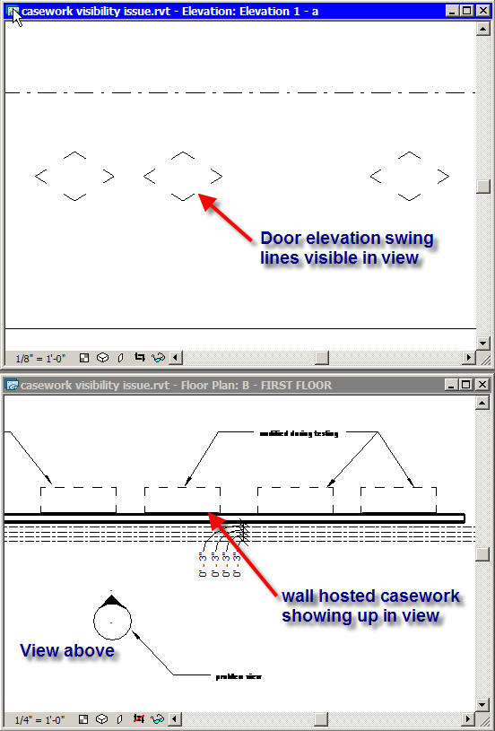
When creating parametric families we've found that the best way to control the dynamic geometry is to create a skeleton of reference planes to which dimensional parameters are attached. Once the skeleton works as expected we create geometry that we attached and lock to the reference planes. However recently we've discovered one minor issue that family authors should be aware of when using reference planes in creating families. On several occasions we've had symbolic geometry randomly showing up in views where it shouldn't. For instance an interior elevation had casework door elevation swing lines showing up when the cabinets were on the other side of the wall (see figure to right). Or, we've had door elevation & plan swing lines show up in views where the door isn't visible. The culprit in all cases has been "extra" reference planes that aren't being used in a family. What makes it even harder to track down is the offending reference planes are often in nested families. In both cases of the casework doors and regular doors it was a piece of hardware that was causing the problem. The hardware was created a "generic model" and the template used included some pre-defined reference planes that weren't required for the handle, because the reference planes were pre-defined they couldn't be deleted, and the author simply left the planes where they were. In the case of the handle, even though the planes were only a couple of feet away (see the figure bottom right) from the origin the handle was so small that it caused problems. In this case the solution was to move the reference planes in extremely close to the geometry so as to stop causing problems.

Cheers,
-R