Saturday, May 05, 2007

Better & Easier Detailing thanks to Object Override

As some may know Rvit 2008 allows you to override and object's graphic style at the object level now, and not just the category and subcategory level. If you actually think about this concept for a moment, it actually breaks all the rules of databasing and Revit, because an object isn't dependent upon the group it belong to to drive its appearance. This means that you could end up with many objects all over your model, that should theoretically look alike, but don't actually, because their properties have been overridden at the object level. (think of what happens in 2D CAD when each person decides to make their own layer for walls, now a project with a 6 person team, has 6 different layers for walls, ahhhhh!).


All that said, the tool is helpful when used in moderation. If you find that you're needing to use it often I would say you need to revisit how the family is built, or how you're manging your family types, categories and subcategories.


Where I see this tool being particulary helpful is in detailing. It always drove me crazy in Revit that you either had to build detail components with all sorts of additional subcateogories (which made it hard to manage) or you had to use the linework tool to get detail components to look just right, and then, depending on view scale it might be even more difficult to manage since in one scale the component might look right, but in another not so much.


Now with this tool the problem is solved. You can quickly drop a component into your view (that you're detailing) and quickly adjust how the component looks in that particular view. Since we're dealing with detail components, I'm actually completely OK with having their graphic appearance be completly unmanaged. Since they are 2D elements they're not real model elements, so we're not depending on them from a database stand point, we only want them to look good in the detail view we've used them in.

Yes Virginia, there are match lines in the Revit world...

So, it seems my last post inspired a comment! (you all still care! :) ). To answer the question, yes in Revit 2008 there is support for a new family (not sure of the exact name) for creating inteligent match lines, which complements the new feature called "Dependent Views".

More on dependent views: Dependent Views allows you to establish a single view (per what we normally would do in Revit). The view can then have as many (there doesn't appear to be a limit, except for file performance) child or "dependent views" as you like. These child views can be cropped however you like, and for better or worse you can turn objects on or off. The one catch of course is that all views, parent & children, must remain at the same scale. To create a dependent view right click on the view in the project browser and goto "duplicate view" there is a new choice to duplicate as dependent.

The new family type "view reference" which is an annotation family, can inteligently report what sheet another child view is on when cropping your dependent views differently because your building is too big for a single sheet. All of this functionality is documented in the new help (I've used it.... :) ).

HTH,
-R

Tuesday, May 01, 2007

Construction Administration & '08 Dependent Views

As you may know Revit '08 has a new feature called dependent views (See Steve's most recent blog post). I'd been planning to make this post for a couple of weeks, but Steve (as usual) has spurred me to action (though he probably doesn't realize he has that affect on me). The most obvious, and apparently intended use of dependent views is for us poor saps that design and build projects that don't fit on standard sheet sizes (where are those 80" plasma screens in the construction trailers....?) where we need to split plans across multiple sheets. Needless to say you can actually split any type of view accross sheets.
However, quite conviently dependent views gives us the ability to do something we couldn't do before, place a single view on multiple sheets. Where I see this as being particularly helpful is in Construction Administration. Often times we need to issue a revised drawing on a smaller page size, for instance a modified detail. There's no need to re-issue a whole sheet, we just need to issue the detail as a sketch on 11x17 or 8.5x11. With dependent views you can create a child view of the detail and place the child on a sketch sheet, leaving your original detail on its original sheet. This preserves your original callouts for the detail, and means that you don't have to duplicate the detail to have it in two places.
The reason I've focused on details though is that there is one slight catch with dependent & parent views, you can't change the scale of one from the other. All primary and dependent views must share the same scale (which follows with expect Revit behavior). You could not then re-issue a scaled version of a plan or section, unless you placed it on a larger sheet, and scaled the print out of the sheet (you'd have to create a custom viewport title family where you could manually set "Scale"). However, if there were a smaller portion of a revised plan that you wished to issue you could create a dependent view, crop it and place it on a sketch sheet.

I hope this gives you some ideas of things you can do with dependent views, besides boring old matchline. :)

-R

Ugh... so long...

Its May 1st! I didn't even manage to post monthly! The E-Specs demo in April went great! We had about 25 people of all types, Project Managers, Spec writers and techies/staff architects like me! Our next meeting will be May 10th at KlingStubbins.

I submitted yesterday to teach a course at AU, hopefully they'll decide to like my idea(s). I'm also working with another popular Revit Power user, so hopefully they'll take us. :)

Cheers,
-R

Saturday, March 17, 2007

E-Specs Demonstration

As part of the new Philadelphia Revit Users Group we will be hosting a
presentation by the makers of E-Specs on Monday evening April 9th. This
will not be a sales presentation by any resellers, rather it is meant to be
an informational gathering.

I encourage all Revit users (arch/struct/MEP) to come out. Also anyone
interested in Revit and some of the powerful uses of the BIM model should
come too.

For more details and to RSVP please go to the Philly Revit Users home page
whose link can be found in the left hand navigation bar.

Thank you,
-Robert

Tuesday, March 13, 2007

Smart Geometry

Recently (well in the last 2 months) I had the opportunity to go to a one day conference in New York City titled: Smart Geometry 2007. The conference was partially sponsored by Bentley Systems, makers of Microstation and other products. (Now I know my blog's title uses Revit, but really I'm interested in all things BIM). The conference was focused on the use of some relatively new software that has been built on top of Bentley's Microstation platform: "Smart Geometry". This software is a very dynamic and parametric software package that has the potential to allow a user to build extremely flexible, rule driven models. Unlike Revit where the programmers give the user certain access to certain functions with regards to control of your model (whether you're in a project or the family editor), Smart Geometry essentially gives you control over just about anything. When you're working in Smart Geometry it's part coding and part 3D modeling. The potentially uses of such a platform are near limitless, anything which has rules to it can be "modeled." Some of the current applications are: stadium design & seating configurations, curtain wall panel size optimization, structural design and derivation for export to analysis packages, form design and modification based on rules (FAR, proforma, programmatic requirements), adaptable and manipulatedable skins/shells. You can learn more about this unique software here:

http://www.smartgeometry2007.com/

There are some very intriguing possibilities with this unique and powerful software, and I firmly believe that it is simple another tool in our chest of BIM tools.

Friday, March 09, 2007

Its been awhile... Using your Project Browser & Project Template

Yes I know, I've been AWOL for quite sometime. quite busy here are my firm, so that is how life goes sometimes.

Recently I've been working on several project, news doors, re-visiting standardized casework and updating our project template.

Today I want to focus on a very minor change I've made to our project template. I've added two shared parameters, one called "view classification" to which it is assinged views, and the other "sheet classification". The purpose of these two new parameters is quite simple, it allows us to sort/filter our project browser by both. In the case of views, each view would get classified under 4 or 5 typical "categories"; Coordination, Presentation, Documentation, Working and CA (Construction Administration). While similiar information is conveyed in a number of ways via a number of other parameters in views, this makes it very easy to set up a Project Browser filter to quickly sort out all the views under these "global" headings. Coordination views would be preset views that would generally be exported to DWG for coordination with outside consultants. I think the next two speak for themselves, Working are the views that we encourage team members to actually "work in", this is typically quite important for floor plans, and sections (where your docuementation sections might be split and moved with break-lines added, etc...). Construction Administration is of course for the random extra views that get created during that process. Teams are welcome to define different, new or more classifications as they see fit. For sheets we start the team out with two classifications, Documentation and Presentation, I suspect however that most teams will find it handy to create a third "CA" when the time is right for their project. Once again the intent here is to get a team started by providing a simple set-up in our projec template. Hopefully teams will take this concept and run with it, and make it their own.

Cheers,
-R

Wednesday, January 24, 2007

The origin of trouble

This issue was reported to me by a fellow Revit user.

The user had created some door families that had a user named reference plane with the "is reference" property set to either strong or weak (he had already used Revit's pre-named reference planes). He used this reference plane to define the origin of the family, as well having a dimensional constraint to the reference plane. When he attempted to switch the family in a project with a similiar family he received constraint error messages causing the family(s) to fail.

This an edited response from Autodesk support:

The only stable references in the family instance are those produced by reference planes designated as named references (that is top, bottom, right, left, etc...). In the families that you created the reference used for alignment (and assigned to define the origin) is a weak reference in both families (referring to families submitted to Autodesk), so it's unstable, and the dimensional parameter fails when the family is replaced (via the type selector in a project).

They (Revit factory) have edited both families and set "Is Reference" of the Reference plane to "Right". Now the reference can be aligned and the instance can switch families.

To sum it all up, use the built in "is reference" names to define reference planes that will also define the origin for the family.

Hope you all find this helpful.
-R

Tuesday, January 16, 2007

A couple of thoughts on walls

We've had some questions come up regarding wall joins. As is typical I can't manage to recreate any actual problems, but I can illustrate some of our general reccomendations to deal with wall join problems.


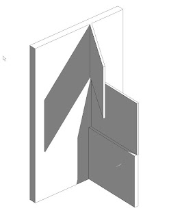
One of the biggest causes of wall heartache comes from wanting to construct our models in the way we think of our buildings (which makes sense when we're supposed to be virtually building the model). However, in conditions where we think of walls as being continuous vertically, we tend to create more problems for ourselves. Revit doesn't really like it when you have vertical walls that run across multiple levels & and multiple walls that go from level to level intersecting the continuous wall (see image to right).


Now, as I said at the beginning, I wasn't able to actually re-create any problems. However, in my experince I've seen similiar situations create problems with the wall join conditions. Revit gets confused about how it should be resolving the various join conidtions (especially if the walls have different materials and layers).


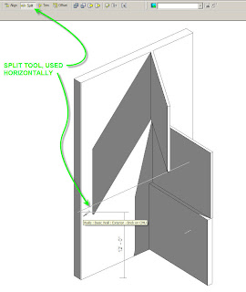
The easiest and quickest way to resolve this issue is to use the split command (thats right, it will work horizontally). I tend to find though that it works best in a 3D view. I usually like to split the wall approximatley where I need to seperate the wall, then I go back and make numerical adjustments in the properties of the wall "pieces". (See image below)


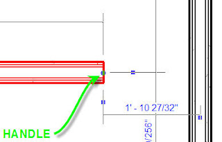
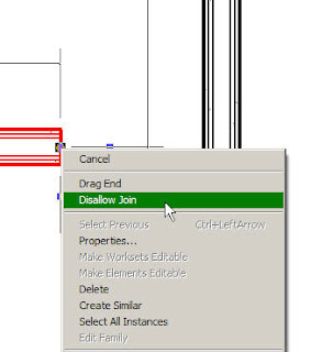
Another thing that is quite helpful (especially with curtain walls) is you can choose to dis-allow joins on specific wall's ends. When you select a wall you can right click on the blue handle at the end and you'll get a context specific menu. One of the options is to "disallow join" this will prevent Revit from attempting to automatically resolve the wall join conditions when two walls meet.


This is particularly helpful when dealing with curtain walls. Curtain wall join conditions can get particulary harry, especially when embedding curtain walls into basic walls, or working in corners.


However, when you do use the "dis-allow" join setting, graphically the walls won't clean up correctly. To fix this you can use the "join geometry" command from the tool bar. This command will force Revit to grapically clean-up the linework, however it won't effect the setting "dis-allow join". There is a difference between Revit's automatic resolution of wall geometry "wall joins" and the the effect(s) of the "join geometry" commnand. See the images below for the "dis-allow joing command. The image on the left shows the blue handle you need to right click on, the image on the right is the context menu.


Tuesday, December 05, 2006

Job Opportunity (position filled)

The job has filled, thanks for the interest.

So.... my firm (whose name I tend to leave off this blog) is seeking a highly motivated proffesional to move to our foriegn office to provide (I hate to say it) 2D Autocad management, and...... BIM & Revit management. We have recently launched our first Revit projects in the office (see earlier blog post), and the staff is very excited to begin using this new tool. Right now we have architects, interior designers and structural engineers working in Revit in our overseas office. The office is composed of highly motivated staff working on some of the largest and most interesting projects in the country. The ideal canidate should have experience in managing 2D CAD, experience with Revit and be highly motivated to work with a BIM implementation team to move our 700 person firm towards 100% use of BIM by.......... (trust me its soon) :).

Please feel free to contact me via AUGI private message, or contact the firm directly.

Cheers,
-R

Follow-up to AU class on roofs

Hey all, had a great time at AU in Las Vegas! At least one picture of me and several other folks have made it on to the AUGI website. I got to attend Scott Brown and Scott Davis' class on creating roofs. I don't usually do straight forward tips & tricks but here is a little of my own follow-up for their course.

During the class the guys showed how to create a roof using a mass element, this is handy for unique conditions, or repetitive unique condidtions, like roof crickets, or warped/sloped flat roofs. In their example they used a blend to create a more unique condition, however for my little tutorial I used some blander mass shapes to create my roofs.


I started by creating a mass object that represents the reptitive portion of my roof.
Then I created a roof by face and grouped the roof. From there the group can be arrayed.


Once the first group has been arrayed you can go back and modify the mass, and create a new roof by face. Group the new roof, then you can select your remaining groups and change the group type to match your new group.

The advantage of this methodology is that for a repetitive roof element you only have to manage one mass object, as opposed to defining multiple mass objects. You can even rotate, move and mirror the group throughout a model. You can't include the mass object in the group, as the roof by face command can't re-create the roof object, it looses its assoication. If you're not going to need your old roof object make sure to delete the group. While groups can sometimes be problomatic with large number of elements, you should not encouter too many problems with some simple roof elements. This technique should prove especially useful for any project with large repetitive roof structures.

Sunday, November 26, 2006

See You at AU

Starts tomorrow (Monday) for me. Look for my AUGI avatar!

Cheers,
-R

Friday, November 17, 2006

Foriegn Training


Ahhhh!!!! Since the beginning of the month things have just been crazy! I was in one of our other stateside offices to give advanced family training to our MEP engineers who are starting to explore Revit systems, and now I'm in our foreign office for about a week to do Revit training with a 20 person team to kick off a new Revit (and first) Revit project here. Thankfully I'm not alone trying to teach 20 people, but the experience has been great! We already have them working in their project files! I've attached a couple of my very poor night pictures, so if you can figure out what its a picture of, you might have chance of determining what country I'm in! In any case I'm back in the states next week (Tuesday) then Thanksgiving, and then AU! I'm looking forward to AU as an intense vacation!

One of our biggest problems in hopping the pond to our foreign office is that we have very little custom Metric content. Though we've very quickly got a project template started for them, and we are working on a titleblock, buts its all very fast and very insane. Before leaving I will be teaching my intensive family training course to users who hadn't even touched Revit until this past week!


Cheers,
-R

Friday, November 03, 2006

Philly Revit Users group

Some of us are trying get something started in the Philadelphia area by way of a dare I say it "users group" while nothing very official right now. Please feel free to sign up for the Google Group we've set-up, trying to plan some sort of happy hour for the first week in Decemeber, before the holiday crazieness takes off, but after AU.


Google Groups Beta

Philadelphia Revit Users

Visit this group

Tuesday, October 31, 2006

Integrated Practice

This morning I had a chance to go to an AIA breakfast on Itegrated Practice (IP). It was led by Norman Strong, FAIA. Most of the people in attendance were prinipals, owners and managing partners of architectural firms from around our area. The great thing about this talk was that it was focused on how BIM allows IP, and how in reality to fully immplement BIM, and your BIM tool of choice, a firm must realize that what is required is a change in the way we practice. Firms cannot rely on their IT person or deptartment to immplement "BIM" IT can certainly help and support, and lead the training on a specific tool. However, should we fail as professionals to realize that we must alter our approach to practice then "BIM" will never be more than a glorified CAD package. An interesting point made by one of the other speakers at this morning's engagement was that when the industry transitioned from hand drafting to CAD the "experts" promised 3%-5% improvement on our productivity, however when you do all the math, we haven't really improved our efficiency. This can lead to two conlusions, a) either CAD did nothing to improve our efficieny, or b) as business people we managed to find a way to give away any improved value/productivity that resulted from our adoption of CAD. This is extremely troubling. Not only do we need to determine how to change our practice, but in doing so we also need to determine how to maintain our value, while sharing risk & reward, so that our clients and consultants see the value we can and do provide.

-R

Monday, October 30, 2006

Yet another Blog graces my links list :)

Yes, if you are a regular reader of Revit & BIM blogs, you probably already know about James Van's blog. He was nice enough to leave me a comment, so I'm returning the favor by linking to his blog, "All Things Bim".

Thanks to the new RevitCity 2.0 for also posting a link to my blog!

-R

Thursday, October 26, 2006

Tracking Your Families

I thought I would share a technique we've appplied to all of our family creation which helps a little bit with keeping track of families, and knowing where they came from. In any new family that gets created at my firm, or if a family is downloaded from a site like RevitCity or AUGI, we ask that the users add three text parameters under the "Identity Data" heading;
  • Version Number
  • Source
  • Author

In the case of creating a new family in the firm, version number would typically start at 1.0, Source would be the firm's name, and Author would be the author's name. For families that are produced by contracted consultants, Source would be the consultant's name, and author the employee of the consulting firm that creates the family. For downloaded content, source would be the website and author would be whatever the username is of the contributing "original" author, or as best can be determined. As part of integrating these three parameters with the process of creating new families we are planning/hoping to add them to all family templates so that the end user merely needs to be concerned with filling the parameters out. When creating new families in our firm we also require end users to provide a description, an assembly code (when it makes sense) and a keynote (also when it makes sense).

Why go to all this trouble? The tracking parameters help us to know where a family came from if it is in circulation. If we have the author and a version number we can to a certain extent more easily track down problems. If the author still works for us, we can just go back to them, version number helps, because there might be a more recently updated family that addresses the problem the user is having with the family. By requiring the descriptive data we are "future proofing" ourselves as we use E-Specs more, or if we work with contractors or other consultants where this type of data can be important, or if we figure out new and innovative ways to make use of the data.

We also include a version number in our Project Template file, which exsists as a project parameter under Project Info, no end user is ever going to bother touching it, and most people probably won't ever notice it. However, once again, if there is a problem with the template we can know what version the template is, furthermore everytime the template is updated we have an excel file where we track the version numbers and changes, thus, we can know what might be missing from an older template and or what needs to be updated to resolve an inherent problem with the template.

There is one downside to the "versioning" of our families, when reloading, even when "overwrite parameters of existing types" is selected the version number does not always update, which is rather unfortunate, as it makes it harder to track what version of a family is loaded into a particular project. Hopefully in the future Autodesk will provide some resolution to this issue.

Thanks for reading,

-R

Wednesday, October 25, 2006

New Search Tool

Google has released a new custom search tool. I've added it to my blog to the left. Right now it searches a very limited number of websites. Over the next few days (ahhh, weeks... :) ) I will try to tweak it. I've given it a limited number of Revit related keywords which are supposed to help with the search results. If you give it a try leave a comment and let me know what you think. If you post a url of a Revit website I should be searching it will make it easier and faster for me to add to the search.

If you're a fellow Revit or BIM blogger (and I know who some of you are) and are interested in collaborting on building the search, and including it on your own blog, drop me a comment, or if I've already been in touch with you via other digital communiques contact me that way.

Cheers,
-R

Monday, October 23, 2006

Improving Family Performance

There is a very simple method that can be employed to improve family performance when loaded in a project, the technique makes it much easier for Revit to "draw" views as it doesn't have to calculate anything with regards to cutting through the family's geometry. Using symbolic lines to represent what the family looks like in a specific view type (plan/RCP, elevation front/back, elevation left/right) with visibility settings set to turn off 3D geometry, allows Revit to automatically render the symbolic lines in the particular view, and ignore the 3D geometry. Revit doesn't have to calculate what the family might look like if it is cut by the view plane, or even if the family is being cut by the view plane, it simply displays the symbolic geometry. However there is one slight hitch, if you're working in any type of 3D family, and draw symbolic lines, when you place the family into a project you'll "see" right through the family! See the image to the right.

To fix this problem you need to create a detail component and nest into your 3D family. Detail components (2D geometry only) allow the use of filled regions (which thankfully can block patterns!). If you create a parametric detail component with a filled region, you can then nest it, and attach its parameters to the parameters of the 3D family. Once this is taken care of you can succesfully load the family into a project and get the results of the table on the left.

I highly reccomend creating a rectangular detail component with a filled region, with the lines set to "invisible", you can then use this component in a variety of situations. If you do not want the filled region to have a pattern or color, make sure to set the type properties of the filled region to "no pattern" and not a solid fill color. If however you want a material pattern you can choose whatever you like. You may also want some filled region detail components for other common shapes like circle, L, etc...

Setting the parameters to instance based will give you shape handles when the component is loaded that can be quickly grabbed & locked. These filled region detail components can be handy for detailing in project views too, rather than having to always create filled regions every time you need one. Instance parameters will make it so that you don't need multiple types.

Wednesday, October 18, 2006

New blog (though you've probably already seen it)

Because I like what she has to say, I've also joined the chorus of fellow Revit bloggers and added Laura's blog about using Revit in the contracting world to my list of links. Thanks to David & Steve where I found her, don't know who was the first one to pick up on her blog. Hopefully my firm can do some work with Tocci, seeing as we have a Boston office....

Here's to Revit!
-R