Early voting results for AU Unplugged have been released on the BLAUG.
I'm pleased to say that my proposed session is in the list. If you haven't please check-out my session and the AU Unplugged wiki in general:
My Session
Wiki
Wednesday, October 31, 2007
Monday, October 01, 2007
AU "Unplugged"
AU unplugged has gone official with a real website. Check it out.
http://au.centraldesktop.com/auunplugged/FrontPage
http://au.centraldesktop.com/auunplugged/FrontPage
Sunday, September 30, 2007
Interesting Note on importing View & a bit of non-Revitness
Pause in Revitness;
Whohooo! The Sox clinched the divsion and so did the Phillies! Now as long as the Boston wins the series, and the Phillies loose the league, I won't have any conflicts of interest, ;)
Pause over.
I went to load some schedules from a previous file into a new file and learned something interesting. It would seem that when you click on that wonderful option to insert views (File menu-->Insert From File-->Views). You're actually opening that whole file in memory on your local machine. Some (like me) may have thought Revit simply had a nifty way of querying other Revit files for their views. That is not the case it would seem, the reason I'm thinking that the whole file is being opened, is because of the message I received. When I selected my file, and hit Open, after it had loaded up, I got a message "Instance of Linked file needs coordination review", what!?.. The file I was working in, doesn't have any linked Revit files, and certainly none that need review, but I know for the fact that the file I wanted to grab views from does have links, and they do need review. Why does this matter? If the entire file that you want to take views from is being opened, that means what you're doing is no different, then if you went to the open command. So the question you should ask yourself, given your computer's hardware specs, when you go to get those views from a file, would you typically open both that file, and the file you're working in at the same time? Something to consider, especially if you dealing with large files. An alternative to transfer views and such, would be to create a new empty file, transfer the views you need into that file, then transfer from the new file to the file that needs the views, thus reducing the load on your computer.
UPDATE:
So, not only does Revit open the entire file in the background (when doing "insert views") the file apparently remains in memory (for how long I don't know yet). I managed to figure this out because I went to do a "transfer project standards" and to my suprise, the file that I had inserted views from, was in the list! And, as you may also know already any files that are linked into a file, were also in the list! This means that you should definently use the Insert from File command carefully, and under strict conditions, or you may be running with a much heavier Revit then anticpated.
Thursday, September 06, 2007
AU "Unplugged"
You may have heard of the "un-conference", well the organizers at AU have decided to do something similiar. (Though I question how "random" and "spur of the moment" it will be with it being so "organized"). Editorials aside, essentially AU Unplugged will provide for small dicussion groups focused around user driven topics. I've submitted a topic inspired by a recent post on AUGI under the "AU class wishlist thread" in the Revit community. I'm suggusting a discussion on best practices for core template & content development, and distribution to the rest of your firm. Vote for me! :).
You can find out more here:
http://au.autodesk.com/2007/blogs/view/AU_Unplugged_is_Ready/
Cheers,
-R
You can find out more here:
http://au.autodesk.com/2007/blogs/view/AU_Unplugged_is_Ready/
Cheers,
-R
Follow-up to Type Catalogs
 Justin had a question comment, and I'll try to respond. I've posted two screen shots, one of the type catalog in Excel, and another of the family types dialog box from a related family (in this case lab casework). You can see in the Revit screen shot the parameter "Rear Panel Access" essentially we want to be able to turn this on or off, as any cabinent can include an access panel, but they don't have to.
So rather then having two different familys, we use a "Yes/No" to control the visibility of some symbolic lines, and also fill in a shared parameter than can be scheduled to indicate if an access panel is required. (make sure to click on the images to get the full size image to see the details).
Breaking Up is Hard to Do
Had a problem today, where a user simply could not successfully move an element "down" (screen direction, in plan). They could move it side to side without a problem. In this case the element to be moved was a linked file, however as far as Revit is concerned, in some ways a linked file is just single large object/group. Having no success in figuring out what to do, I defaulted to my old standby trick to break any sort of constraint; "cut" (cntrl+x). The cut command has the wonderful ability to keep everything on your clipboard, but all relationships or constraints between the object you cut, and the rest of your model are completely broken. With a quick "paste aligned; same place" (under the edit menu) we were able to place the cut object back in the same exact spot, then move it down the 8" required. How the linked file originally got out of place we don't know (I highly reccomend pinning cirtical elements like links, grids, levels).
This trick of cutting, and pasting back to the same place is also effective on sketch lines or other objects that like to automatically establish relationships with other objects. On more then one occasions I've had to cut and paste the sketch lines of either a floor or ceiling in order to prevent the floor or ceiling from attempting to adapt to changes in wall configurations.
This trick of cutting, and pasting back to the same place is also effective on sketch lines or other objects that like to automatically establish relationships with other objects. On more then one occasions I've had to cut and paste the sketch lines of either a floor or ceiling in order to prevent the floor or ceiling from attempting to adapt to changes in wall configurations.
Sunday, July 29, 2007
Type Catalogs
As some of you might be aware, when creating Revit families you can also author a type catalog to go with your family. Type Catalogs are extremely useful if you are going to have any sort of parametric family that is going to have many types. My general rule of thumb is if you need six or more types, then you need a catalog (I confess that I learned this from someone else somewhere along the way, JB, PR & others). If you want to know how to format your own basic type catalog in Revit just go the Revit Help and do a search for "Type Catalog", I promise you'll find something. In any case, while the help instructions get you started, they don't really cover everything in detail. For instance, it spells out the basic "unit" types allowed, but in their own example you can an "other" column created, which allows them to assign text strings to the "Model" parameter of their example. What I've been working on required the use of "Yes/No" parameters in the family type, furthermore, I wanted to specify the condition of the "Yes/No" in my catalog. I started with the other, and assuming that Revit simply would interpert text, I inserted Yes or No. Needless to say (otherwise I wouldn't be writing, ;) ) it wasn't that simple. When I went to load my 40 some odd types, I got 40 some odd warning messages referring to my Yes/No parameter.... hmmmmm. Well first, since Revit is always so case sensitive I changed all my "Yes" and "No"s to "yes" and "no", same problem... Then I sat back and said, hmmmmmmmmm, Revit is a computer program, and from working with Yes/No parameters in conditional formulas, I know that its really a binary switch (hang on there, I know I'm delving into compturese....), which really means, even though in a schedule Yes/No's show as "Yes" or "No" as far as the computer & Revit are concerned, its really, true or false and if its really true or false, that means its a "0" or "1", just like computer programming. Soooooo, I decided to put 0's and 1's into my Type Catalog. Bang!! It worked perfectly! My types came in without any warnings, and the Yes/No parameter was "thrown" correctly, ie Yes or No where needed. This little un-documented bit, really makes me wonder what other little things are hiding, hidden under the veil of more typical computer programming, rather then a more "user friendly" format.
Tuesday, July 24, 2007
Backups in my Journals! What!!!
So, a new feature that some people may not be aware of in Revit 2008 (supposedly its published somewhere, but I don't remeber reading it). I found this quite accidently when I was messing around with journal files for something else. In the journals folder I found all sorts of rfa and rvt files. At first I thought, maybe Revit creates a Revit file when it crashes and creates a dump file, however that didn't really make very much sense. An inquiry to my contacts at Autodesk revealed the truth. Revit now creates backup files under the journals directory in c:\program files\revit 2008\journals, these backup files are only created when you're working on a file located on a network share or drive. As you can see from my screen shot, I do a great deal of working on networked based files! I will add that this new behavior is not applied to files with worksharing enabled, so no worries about all sorts of duplicate copies of your local or central files being created. That said none of your families are going to have worksets, and in my expereince I'm always working with various experimental files that are not worksetted too, so you may want to keep an eye on this directory. My "problem" with this new behavior is further compounded because I use a piece of software called I-Share Mobliti, its a really great tool in that it essentially replicated (and manages) network resources to my local harddrive. Unlike other tools out there, this tool actually creates a virtual network, so as far as my computer is concerned, I'm always working on the network. This, however creates a problem for me, since my computer thinks I'm on the network, Revit thinks I'm on the network, thus creating all sorts of back-up files. At this time, there is no way to modiy this built in behavior, I wish there were some sort of tweak for the ini that would at least allow you to re-path the directory, however for the moment we're all stuck.
Sunday, June 24, 2007
New Revit website
Following on Steve Stafford's post, and the fact that Ian left me a very kind comment as well. I've added Ian's new "Revit Zone" to my links list. Looks like the site could be quite helpful and so far very well done (nice looking graphics).
Cheers,
-R
Cheers,
-R
Saturday, June 23, 2007
Fun with VTF (Variable Thickness Floors)
So yes, undoubtedly we were all quite excited to see this feature (VTF - Variable Thickness Floors) enter Revit Architecture 2008 (development thanks to our structural friends). If you don't know or didn't realize, Revit '08's floor can now be set to slope or warp in multiple directions even though the floor is still essentially "flat", this is particularly useful for crickets, tapered insulation, warped/sloped concrete decks and parking garages. This is all well and good, but a use that may have not yet been considered would be to use VTF for creating site or topographic elements.
 Huh!? you might say... Check it out... My current project we have this "courtyard" or "quad" that has significant change in elevation across it (about 5'-7'). The landscape architect's current design includes a couple of sloping paths and some stairs. In addition there are some manicured green lawns that are going to gently slope in one or two directions, all surrounded by masonry walls.
So I decided to create the paths and lawn areas all with VTF's. To start I created thin pads to cut into my topo surface so that I essentially had a hole in the ground for my in-fill.
I should add that the site file in this case is separate from the building file(s). So under all my buildings are 4" thick pads whose material is set to be "gravel". I used the same pad type under the courtyard, though that could change in the future...
 Once my pads were set-up, I was able to create the walls, then the floor objects. Once the floors were in place I could start to use the new tools to adjust the properties of the floor's slope(s).
In this case I chose to have one layer that stays constant (2" thick) then another layer that has a minimum thickness (in this case 4") for a total minimum thickness of 6" for my "grass". Both layers in the floor type are set to the same material so that in sections it reads as a monolithic material.
I also used a second floor type for the "paved" path ways, one note of caution though, when you subdivide a floor object it becomes much more difficult to manipulate the hatch pattern. It appears that the align tool no longer works correctly. You are still able to use move and rotate to adjust the pattern. At this time on our project because the landscape architect will produce the final documents, the non matching tile pattern doesn't bother me much, but I can see where it would cause problems. I suspect that Accurender will have the same difficulty, so at some point, I will probably adjust the hatch patter, and will render with a simple surface material applied (no pattern) and then merge a Hidden Line image with the rendered image to get a paving pattern.
 Once the floors were in place and set-up, I went back and did profile edits on the surrounding walls so that the tops of the walls taper with the slope of the adjoining "grass". Now I've got my courtyard in place in Revit, so that my elevations and sections start to read more correctly, and needless to say I think these results are better then what I would have been able to achieve by attempting to edit the topo surface. As of these images there is still some work to do, I need to put in some stairs, and make some other tweaks, add some flower beds, etc., but its a good start...
Tuesday, June 19, 2007
Wall Schedules
 In case you didn't know. Wall schedules are smart when dealing with areas. If you add a window, the reported area for the wall will be reduced. Obvious really, but I don't trust anything until I've run my own tests...
Why do I care? Today I was working with our energy anaylis team, and they needed to know the ratio of opening(s) in our building to our total exterior envelope. Now of course Revit will happily spit out all sorts of numbers, but how do you know they're right? Hence the testing of wall schedule behavior. In the end we have at least three schedules to help us get the numbers to calculate the ratio. A wall schedule (making sure to exclude all walls except the exterior envelope), a curtain wall schedule and a window schedule (from which we're calculating area).  With those three numbers we can then determine our ratio(s).
 With those three numbers we can then determine our ratio(s).
Wednesday, June 13, 2007
Partition (not wall) Types
So as most Revit users are aware, wall families in Revit can't really be seperated from the project file. Most people (I think) opt to put their firm's standard wall types into their project templates. However, being such a large firm we've opted for a slightly different approach. Because we service so many different market sectors, and have so many offices (up to 8 stateside, 3 international now) we've opted to keep our base project template simple and streamlined. To that end it contains only generic partition and wall types. More advanced (and approved) partition types are instead stored in a project file that is kept in our library. Projects can open the file, and either do a "Transfer Project Standards" or copy/paste the partition types they need. They can also bring over details, partition schedules, and general notes as needed. We plan to create similiar "library" project files for our major market sectors (like healthcare and Science & Technology) rather then creating multiple actual project templates, that all have to be updated when we make minor changes. In this process I've also learned that partitions is what we build inside, and walls go on the outside of a building. The screen shot below is from the partition type file, it is set up with 8 1/2" x 11" sheets so that we can print a partition standards booklet from the file for distribution or reference.

Not wanted... :(
So AU decided they didn't want me :(, I tried! They apparently didn't want a bunch of other people I know too, so I don't feel too bad. With any luck I will still attend AU this coming year, and I'm willing to help anyone out that needs assistance in presenting on Revit. I look at it this way, not having to prepare for AU frees me up to focus on my project work, moving things forward at my firm, and having a life on the side. If you are interested to hear what I have to say on BIM or Revit, drop me a line, I'm always insterested (and motivated) to speak on the subject(s).
Sunday, June 10, 2007
ACEC & AIA Presentations
I recently had the privilige to present at a 1 1/2 day conference sponsored by the ACEC (American Council of Engineering Companies www.acec.org). I presented my firm and my one and only full Revit project (slated to be occupied 09/2007!) as a case study of early adoption of BIM and Revit as our tool of choice. The presentation went very well and I received lots of great feedback afterwards!
I will be presenting at an event hosted by the Philadelphia Chapter of the AIA (www.aiaphila.org) this coming Thursday morning. I hope to build on some of the hot topics (as I've been told) that came off of the AIA national convention. I intend to talk speak about what BIM tools like Revit can do for firms here and now, while keeping an eye towards the future and hopefully a fully "Integrated Practice".
On top of all that the Philly RUG (see link on the left navigation bar) will be hosting its last meeting on June 18th before our summer siesta. Hopefully over the summer we will be able to put together paperwork to become and official AUGI LUG, and the benifits that can be gained from that association.
As you might be able to tell I've been a little busy (hence the lack of blog posts)! I've also submitted to present in the fall for the Philadelphia AIA and at AU in Nov. (keeping my fingers crossed).
Thanks,
-Robert
Why didn't I think of this earlier?
This may be obvious to some people, but it only occured to me recently.

I was tagging rooms in colored plans, and my project manager wanted "big" names, but in some cases, big was going to be too big, so I needed different size room tags. In the past I would have simply created a new family, and modified the label properties. This time however I did things a little different. See the image to the right for what my new tag looks like.
Looks slightly confusing huh? What I did was I copied the label and did a paste aligned in the same location. Then I edited the label to be a new type with a new text size. In addition I manipulated the size of the text box so that in some cases I would get two lines instead of one. Once that was done, I then set the visibility control of each label to a parameter.

I could have gotten really fancy from there with setting up some formulas to control different types. But I opted for simplicity (as it was quicker). So I created a new family type for each tag size, and for each type, the correctly sized label is turned on, and all the others are turned off (see the image below).

The other trick I like to do when labeling rooms is to make use of the comments field. Often on "presentation" drawings we want to abbriviate room names (heck on construction docs we do too), or maybe you want to call something by a more general name, then "Math & Sciences classroom", perhaps simply "classroom" is better and easier (and doesn't raise as many questions with clients! :) ). Hence I use the comments field, so that in my room schedule "Janitor Closet" is called just "JC". To do this I duplicate my room tag and change the labels to point to the Comment's Property, rather then "Name". Between my new and improved tags and the two seperate fields, I have a great deal of flexibility when it comes to labeling rooms on drawings.
Saturday, May 05, 2007
Better & Easier Detailing thanks to Object Override
As some may know Rvit 2008 allows you to override and object's graphic style at the object level now, and not just the category and subcategory level. If you actually think about this concept for a moment, it actually breaks all the rules of databasing and Revit, because an object isn't dependent upon the group it belong to to drive its appearance. This means that you could end up with many objects all over your model, that should theoretically look alike, but don't actually, because their properties have been overridden at the object level. (think of what happens in 2D CAD when each person decides to make their own layer for walls, now a project with a 6 person team, has 6 different layers for walls, ahhhhh!).
All that said, the tool is helpful when used in moderation. If you find that you're needing to use it often I would say you need to revisit how the family is built, or how you're manging your family types, categories and subcategories.
Where I see this tool being particulary helpful is in detailing. It always drove me crazy in Revit that you either had to build detail components with all sorts of additional subcateogories (which made it hard to manage) or you had to use the linework tool to get detail components to look just right, and then, depending on view scale it might be even more difficult to manage since in one scale the component might look right, but in another not so much.
 Now with this tool the problem is solved. You can quickly drop a component into your view (that you're detailing) and quickly adjust how the component looks in that particular view. Since we're dealing with detail components, I'm actually completely OK with having their graphic appearance be completly unmanaged. Since they are 2D elements they're not real model elements, so we're not depending on them from a database stand point, we only want them to look good in the detail view we've used them in.
Yes Virginia, there are match lines in the Revit world...
So, it seems my last post inspired a comment! (you all still care! :) ). To answer the question, yes in Revit 2008 there is support for a new family (not sure of the exact name) for creating inteligent match lines, which complements the new feature called "Dependent Views".
More on dependent views: Dependent Views allows you to establish a single view (per what we normally would do in Revit). The view can then have as many (there doesn't appear to be a limit, except for file performance) child or "dependent views" as you like. These child views can be cropped however you like, and for better or worse you can turn objects on or off. The one catch of course is that all views, parent & children, must remain at the same scale. To create a dependent view right click on the view in the project browser and goto "duplicate view" there is a new choice to duplicate as dependent.
The new family type "view reference" which is an annotation family, can inteligently report what sheet another child view is on when cropping your dependent views differently because your building is too big for a single sheet. All of this functionality is documented in the new help (I've used it.... :) ).
HTH,
-R
Tuesday, May 01, 2007
Construction Administration & '08 Dependent Views
As you may know Revit '08 has a new feature called dependent views (See Steve's most recent blog post). I'd been planning to make this post for a couple of weeks, but Steve (as usual) has spurred me to action (though he probably doesn't realize he has that affect on me). The most obvious, and apparently intended use of dependent views is for us poor saps that design and build projects that don't fit on standard sheet sizes (where are those 80" plasma screens in the construction trailers....?) where we need to split plans across multiple sheets. Needless to say you can actually split any type of view accross sheets.
However, quite conviently dependent views gives us the ability to do something we couldn't do before, place a single view on multiple sheets. Where I see this as being particularly helpful is in Construction Administration. Often times we need to issue a revised drawing on a smaller page size, for instance a modified detail. There's no need to re-issue a whole sheet, we just need to issue the detail as a sketch on 11x17 or 8.5x11. With dependent views you can create a child view of the detail and place the child on a sketch sheet, leaving your original detail on its original sheet. This preserves your original callouts for the detail, and means that you don't have to duplicate the detail to have it in two places.
The reason I've focused on details though is that there is one slight catch with dependent & parent views, you can't change the scale of one from the other. All primary and dependent views must share the same scale (which follows with expect Revit behavior). You could not then re-issue a scaled version of a plan or section, unless you placed it on a larger sheet, and scaled the print out of the sheet (you'd have to create a custom viewport title family where you could manually set "Scale"). However, if there were a smaller portion of a revised plan that you wished to issue you could create a dependent view, crop it and place it on a sketch sheet.
I hope this gives you some ideas of things you can do with dependent views, besides boring old matchline. :)
-R
Ugh... so long...
Its May 1st! I didn't even manage to post monthly! The E-Specs demo in April went great! We had about 25 people of all types, Project Managers, Spec writers and techies/staff architects like me! Our next meeting will be May 10th at KlingStubbins.
I submitted yesterday to teach a course at AU, hopefully they'll decide to like my idea(s). I'm also working with another popular Revit Power user, so hopefully they'll take us. :)
Cheers,
-R
I submitted yesterday to teach a course at AU, hopefully they'll decide to like my idea(s). I'm also working with another popular Revit Power user, so hopefully they'll take us. :)
Cheers,
-R
Saturday, March 17, 2007
E-Specs Demonstration
As part of the new Philadelphia Revit Users Group we will be hosting a
presentation by the makers of E-Specs on Monday evening April 9th. This
will not be a sales presentation by any resellers, rather it is meant to be
an informational gathering.
presentation by the makers of E-Specs on Monday evening April 9th. This
will not be a sales presentation by any resellers, rather it is meant to be
an informational gathering.
I encourage all Revit users (arch/struct/MEP) to come out. Also anyone
interested in Revit and some of the powerful uses of the BIM model should
come too.
For more details and to RSVP please go to the Philly Revit Users home page
whose link can be found in the left hand navigation bar.
Thank you,
-Robert
Tuesday, March 13, 2007
Smart Geometry
Recently (well in the last 2 months) I had the opportunity to go to a one day conference in New York City titled: Smart Geometry 2007. The conference was partially sponsored by Bentley Systems, makers of Microstation and other products. (Now I know my blog's title uses Revit, but really I'm interested in all things BIM). The conference was focused on the use of some relatively new software that has been built on top of Bentley's Microstation platform: "Smart Geometry". This software is a very dynamic and parametric software package that has the potential to allow a user to build extremely flexible, rule driven models. Unlike Revit where the programmers give the user certain access to certain functions with regards to control of your model (whether you're in a project or the family editor), Smart Geometry essentially gives you control over just about anything. When you're working in Smart Geometry it's part coding and part 3D modeling. The potentially uses of such a platform are near limitless, anything which has rules to it can be "modeled." Some of the current applications are: stadium design & seating configurations, curtain wall panel size optimization, structural design and derivation for export to analysis packages, form design and modification based on rules (FAR, proforma, programmatic requirements), adaptable and manipulatedable skins/shells. You can learn more about this unique software here:
http://www.smartgeometry2007.com/
There are some very intriguing possibilities with this unique and powerful software, and I firmly believe that it is simple another tool in our chest of BIM tools.
http://www.smartgeometry2007.com/
There are some very intriguing possibilities with this unique and powerful software, and I firmly believe that it is simple another tool in our chest of BIM tools.
Friday, March 09, 2007
Its been awhile... Using your Project Browser & Project Template
Yes I know, I've been AWOL for quite sometime. quite busy here are my firm, so that is how life goes sometimes.
Recently I've been working on several project, news doors, re-visiting standardized casework and updating our project template.
Today I want to focus on a very minor change I've made to our project template. I've added two shared parameters, one called "view classification" to which it is assinged views, and the other "sheet classification". The purpose of these two new parameters is quite simple, it allows us to sort/filter our project browser by both. In the case of views, each view would get classified under 4 or 5 typical "categories"; Coordination, Presentation, Documentation, Working and CA (Construction Administration). While similiar information is conveyed in a number of ways via a number of other parameters in views, this makes it very easy to set up a Project Browser filter to quickly sort out all the views under these "global" headings. Coordination views would be preset views that would generally be exported to DWG for coordination with outside consultants. I think the next two speak for themselves, Working are the views that we encourage team members to actually "work in", this is typically quite important for floor plans, and sections (where your docuementation sections might be split and moved with break-lines added, etc...). Construction Administration is of course for the random extra views that get created during that process. Teams are welcome to define different, new or more classifications as they see fit. For sheets we start the team out with two classifications, Documentation and Presentation, I suspect however that most teams will find it handy to create a third "CA" when the time is right for their project. Once again the intent here is to get a team started by providing a simple set-up in our projec template. Hopefully teams will take this concept and run with it, and make it their own.
Cheers,
-R
Wednesday, January 24, 2007
The origin of trouble
This issue was reported to me by a fellow Revit user.
The user had created some door families that had a user named reference plane with the "is reference" property set to either strong or weak (he had already used Revit's pre-named reference planes). He used this reference plane to define the origin of the family, as well having a dimensional constraint to the reference plane. When he attempted to switch the family in a project with a similiar family he received constraint error messages causing the family(s) to fail.
This an edited response from Autodesk support:
The only stable references in the family instance are those produced by reference planes designated as named references (that is top, bottom, right, left, etc...). In the families that you created the reference used for alignment (and assigned to define the origin) is a weak reference in both families (referring to families submitted to Autodesk), so it's unstable, and the dimensional parameter fails when the family is replaced (via the type selector in a project).
They (Revit factory) have edited both families and set "Is Reference" of the Reference plane to "Right". Now the reference can be aligned and the instance can switch families.
To sum it all up, use the built in "is reference" names to define reference planes that will also define the origin for the family.
Hope you all find this helpful.
-R
Tuesday, January 16, 2007
A couple of thoughts on walls
We've had some questions come up regarding wall joins. As is typical I can't manage to recreate any actual problems, but I can illustrate some of our general reccomendations to deal with wall join problems.
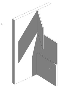
One of the biggest causes of wall heartache comes from wanting to construct our models in the way we think of our buildings (which makes sense when we're supposed to be virtually building the model). However, in conditions where we think of walls as being continuous vertically, we tend to create more problems for ourselves. Revit doesn't really like it when you have vertical walls that run across multiple levels & and multiple walls that go from level to level intersecting the continuous wall (see image to right).
Now, as I said at the beginning, I wasn't able to actually re-create any problems. However, in my experince I've seen similiar situations create problems with the wall join conditions. Revit gets confused about how it should be resolving the various join conidtions (especially if the walls have different materials and layers).
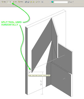
The easiest and quickest way to resolve this issue is to use the split command (thats right, it will work horizontally). I tend to find though that it works best in a 3D view. I usually like to split the wall approximatley where I need to seperate the wall, then I go back and make numerical adjustments in the properties of the wall "pieces". (See image below)
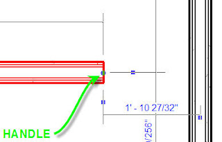
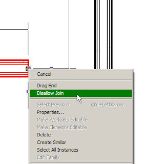
Another thing that is quite helpful (especially with curtain walls) is you can choose to dis-allow joins on specific wall's ends. When you select a wall you can right click on the blue handle at the end and you'll get a context specific menu. One of the options is to "disallow join" this will prevent Revit from attempting to automatically resolve the wall join conditions when two walls meet.
This is particularly helpful when dealing with curtain walls. Curtain wall join conditions can get particulary harry, especially when embedding curtain walls into basic walls, or working in corners.
However, when you do use the "dis-allow" join setting, graphically the walls won't clean up correctly. To fix this you can use the "join geometry" command from the tool bar. This command will force Revit to grapically clean-up the linework, however it won't effect the setting "dis-allow join". There is a difference between Revit's automatic resolution of wall geometry "wall joins" and the the effect(s) of the "join geometry" commnand. See the images below for the "dis-allow joing command. The image on the left shows the blue handle you need to right click on, the image on the right is the context menu.

One of the biggest causes of wall heartache comes from wanting to construct our models in the way we think of our buildings (which makes sense when we're supposed to be virtually building the model). However, in conditions where we think of walls as being continuous vertically, we tend to create more problems for ourselves. Revit doesn't really like it when you have vertical walls that run across multiple levels & and multiple walls that go from level to level intersecting the continuous wall (see image to right).
Now, as I said at the beginning, I wasn't able to actually re-create any problems. However, in my experince I've seen similiar situations create problems with the wall join conditions. Revit gets confused about how it should be resolving the various join conidtions (especially if the walls have different materials and layers).
The easiest and quickest way to resolve this issue is to use the split command (thats right, it will work horizontally). I tend to find though that it works best in a 3D view. I usually like to split the wall approximatley where I need to seperate the wall, then I go back and make numerical adjustments in the properties of the wall "pieces". (See image below)

Another thing that is quite helpful (especially with curtain walls) is you can choose to dis-allow joins on specific wall's ends. When you select a wall you can right click on the blue handle at the end and you'll get a context specific menu. One of the options is to "disallow join" this will prevent Revit from attempting to automatically resolve the wall join conditions when two walls meet.
This is particularly helpful when dealing with curtain walls. Curtain wall join conditions can get particulary harry, especially when embedding curtain walls into basic walls, or working in corners.
However, when you do use the "dis-allow" join setting, graphically the walls won't clean up correctly. To fix this you can use the "join geometry" command from the tool bar. This command will force Revit to grapically clean-up the linework, however it won't effect the setting "dis-allow join". There is a difference between Revit's automatic resolution of wall geometry "wall joins" and the the effect(s) of the "join geometry" commnand. See the images below for the "dis-allow joing command. The image on the left shows the blue handle you need to right click on, the image on the right is the context menu.


Subscribe to:
Posts (Atom)

